


3-Axis vs. 4-Axis vs. 5-Axis CNC Machining: Differences, Accuracy, Applications
Axis count is not a quality badge — it is a motion capability. Here is what it changes, what it doesn’t, and when the expensive machine is actually the cheaper choice.
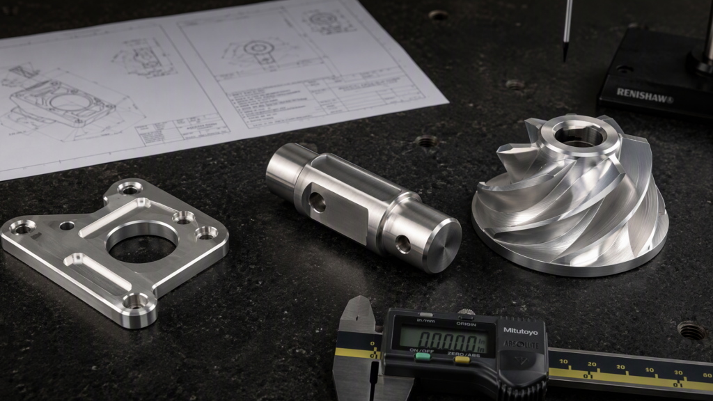
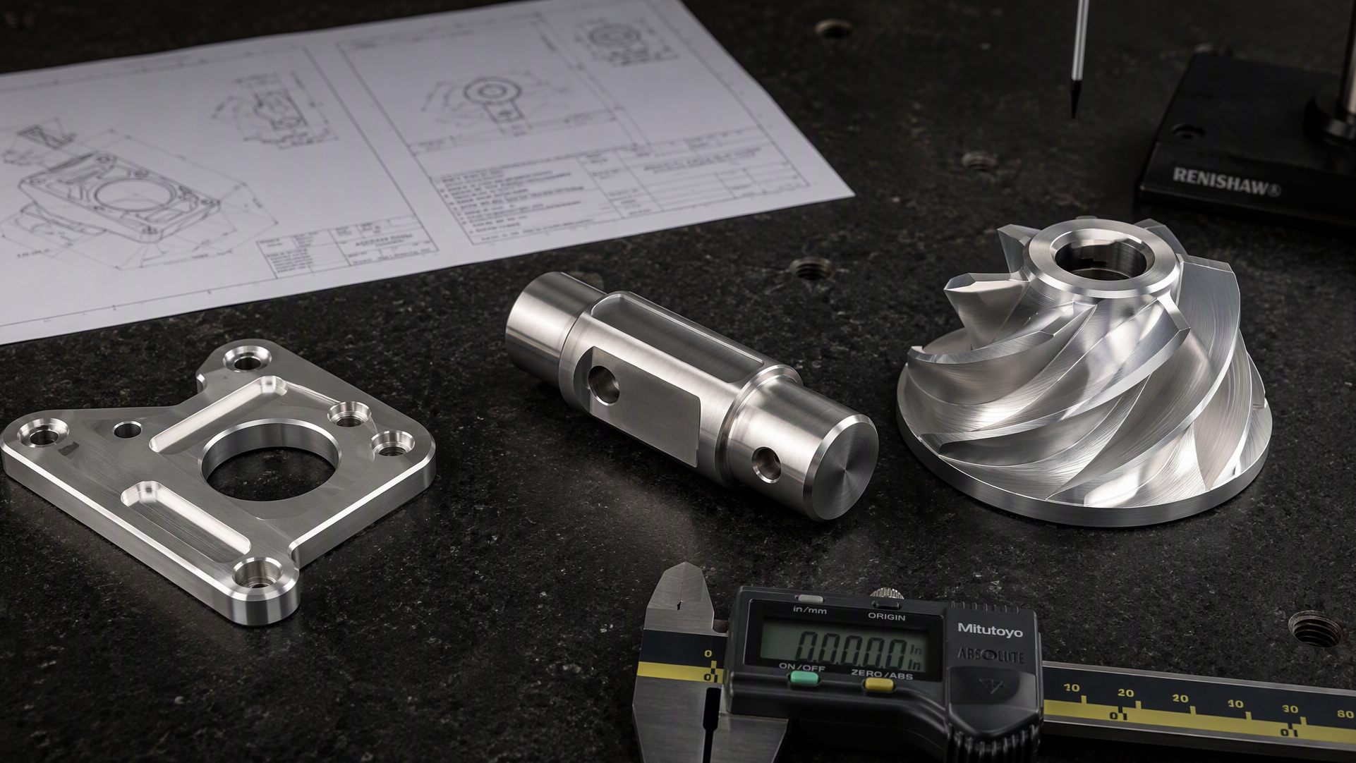
From a flat bracket to a helical shaft to a twisted impeller: complexity decides the axis count.
“Should this part be made on a 3-axis or a 5-axis machine?” is one of the most common questions in CNC machining — and one of the most commonly answered wrong.
The axis count is not a quality badge; it is a motion capability. More axes mean the cutter can reach the workpiece from more directions with fewer re-clampings — which changes accuracy, surface finish, cycle time, and cost in specific, predictable ways. This guide explains exactly what 3-, 4-, and 5-axis machines do differently, the accuracy each can realistically hold, where each is applied, and the precautions that keep buyers from paying 5-axis prices for 3-axis parts (or the reverse).
1. What the Axis Count Actually Means
Every CNC mill moves along three linear axes: X (left-right), Y (front-back), Z (up-down). That’s a 3-axis machine — the industry workhorse, responsible for roughly 65–70% of all CNC machining.
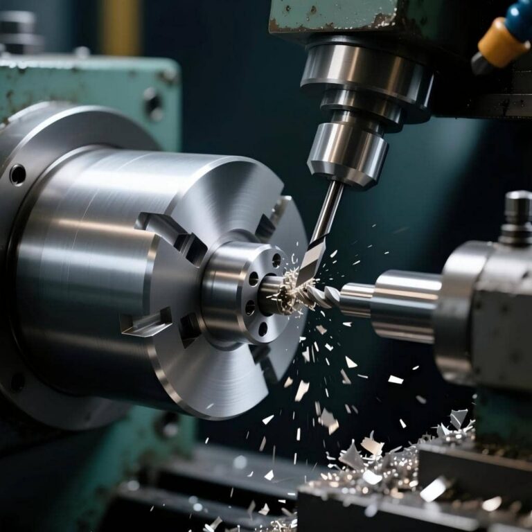
- 4 ejes adds one rotary axis (usually A, rotating around X): the workpiece can spin like a lathe chuck while the mill cuts — ideal for machining features around cylinders.
- 5 ejes adds a second rotary axis (A+B or A+C): the tool or the workpiece can tilt and rotate, so the cutter can approach from virtually any direction — often in a single setup.
One critical subdivision hides inside the word “5-axis”:
- 3+2 (positional) machining — the rotary axes tilt the part to an angle, lock, and then ordinary 3-axis cutting happens. Rigid, simpler to program, and delivers roughly 90% of 5-axis benefits at about 50% of the complexity — perfect for flat faces presented at angles.
- Simultaneous 5-axis — all five axes interpolate continuously during the cut, following sculpted surfaces like impeller blades. This is the expensive, powerful mode that true free-form geometry requires.
2. The Three Configurations Side by Side
| Factor | 3-Axis | 4-Axis | 5-Axis (3+2 / simultaneous) |
| Motion | X, Y, Z linear | X, Y, Z + 1 rotary (A) | X, Y, Z + 2 rotary (A/B or A/C) |
| Faces reachable per setup | 1–3 | Multiple, around a rotation axis | Up to 5 (often the whole part in one setup) |
| Undercuts / compound angles | Not possible | Limited | Yes |
| Continuous sculpted surfaces | No | Helical / cylindrical only | Yes (simultaneous mode) |
| Typical setups for a complex part | 3–5 re-clampings | 1–3 | 1 (sometimes 2) |
| Achievable tolerance | ±0.05–0.25 mm (setup stack-up dependent) | ±0.025–0.1 mm | ±0.025–0.075 mm; feature-to-feature relationships excellent in one setup |
| Surface finish | Good on accessible faces | Good on cylindrical features | Superior on contours — tool stays at optimal angle |
| Programming | Standard CAM | CAM with rotary support | Advanced CAM (NX, Mastercam, hyperMILL, PowerMill) + collision simulation |
| Machine cost / shop rate | $50k–250k machine; ~$45–95/hr | Moderate premium | $200k–800k+ machine; ~$75–175/hr |
3. Accuracy: The Truth Behind the Tolerance Numbers
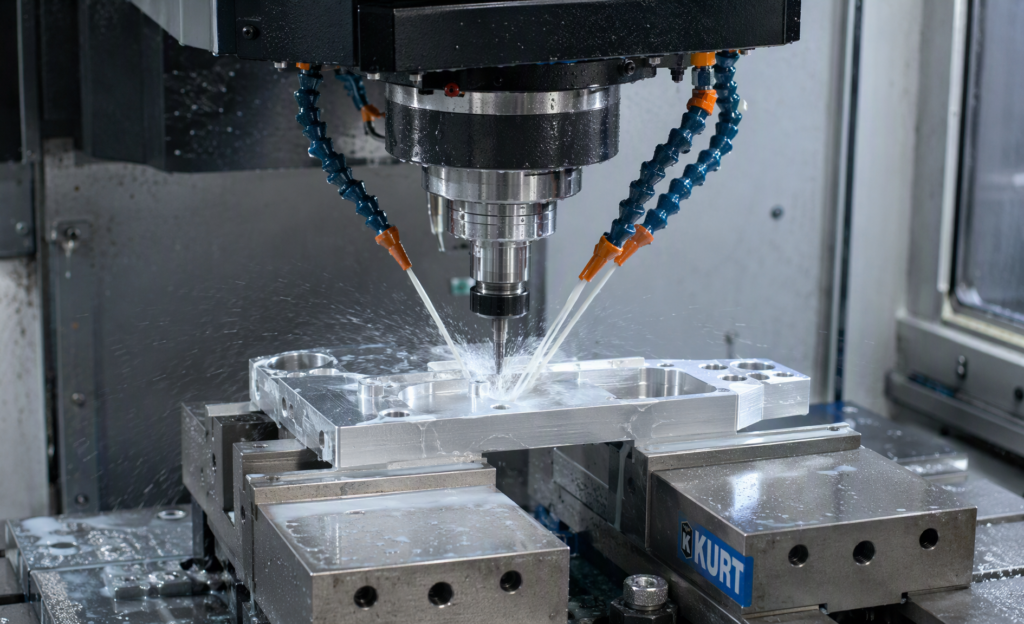
3-axis milling: one face at a time, one vise at a time — every re-clamping adds its own error
Here’s the nuance most comparisons miss: a 5-axis machine is not inherently more accurate than a 3-axis machine. Positioning accuracy comes from machine design, calibration, thermal stability, tooling, and workholding — not from the axis count. What extra axes actually eliminate is setup-related error:
- Re-clamping uncertainty. Every time a part is unclamped, rotated, and re-fixtured on a 3-axis machine, the new setup introduces 0.01–0.05 mm of repositioning uncertainty — and the errors stack. A part machined in 5 setups carries five setups’ worth of accumulated positional drift between faces.
- One coordinate system. In a single 5-axis setup, features on all five faces share one coordinate system. Feature-to-feature positional relationships — the GD&T true-position callouts that actually matter on brackets and housings — hold dramatically better.
A published real-world case makes the point: an aerospace bracket needing 6 machined faces and 4 angled bores was quoted 3-axis at 5 setups — first-article failure rate 18% from dimensional stack-up. Re-quoted 5-axis, single setup: 100% first-pass rate, 38% shorter cycle time, and 25% lower total cost despite the higher hourly rate.
Practical guidance on numbers: on a well-maintained machine with proper fixturing, 3-axis holds ±0.05–0.1 mm comfortably and ±0.025 mm with care; 5-axis holds the same absolute numbers but sustains them across faces, where 3-axis quietly loses them in re-clamping.
4. Applications: Matching the Machine to the Part
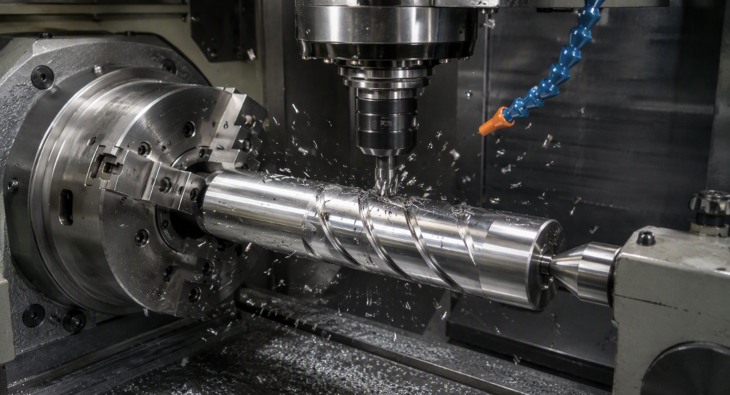
4-axis: machining flats, keyways, and cross-holes around a rotating cylinder.
3-axis is the right choice for:
- Plates, brackets, housings, mounting components, fixtures
- Pockets, holes, slots, flat surfaces, 2.5D profiles
- Simple molds, enclosures, heat sinks
- High volumes of simple parts (500+) where the low hourly rate wins
- Any part whose features are reachable from one or two orientations
4-axis is the right choice for:
- Shafts, gears, cams, and cylindrical parts needing flats, keyways, or cross-holes at angular positions
- Helical grooves and wrapped features
- Box parts needing features on 4 side faces (indexing around the rotary axis)
- Multi-face parts where a rotary indexer kills 2–3 manual setups
5-axis is the right choice for:
- Turbine blades, impellers, blisks — continuous twisted surfaces (simultaneous mode)
- Aerospace structural parts with compound angles and weight-optimized pockets
- Medical implants and bone plates with organic curvature
- Complex mold cores and cavities with deep, curved surfaces
- Parts with angled holes or undercuts on multiple faces
- Any part that would need 3+ setups on a 3-axis machine — the crossover point where 5-axis usually becomes cheaper in total
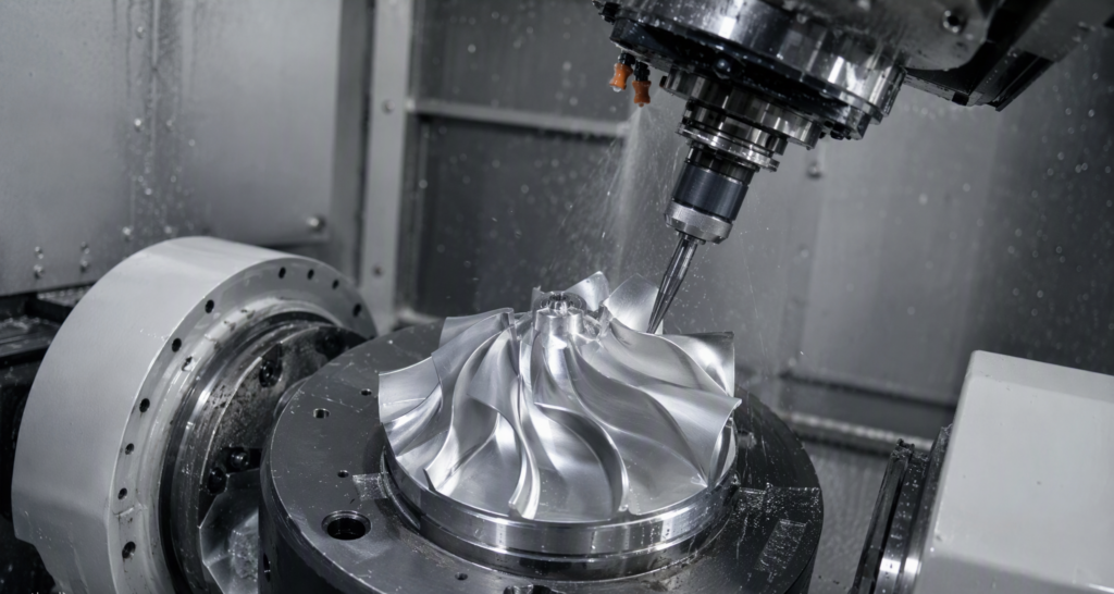
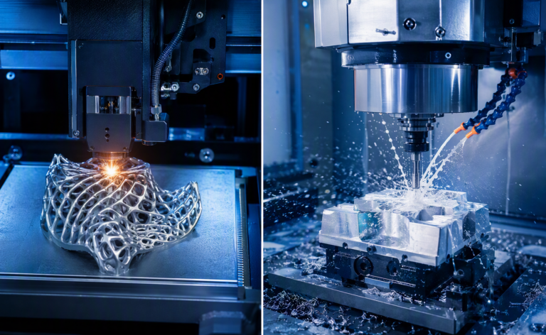
Simultaneous 5-axis machining of an impeller: the tool follows the twisted blade surfaces continuously.
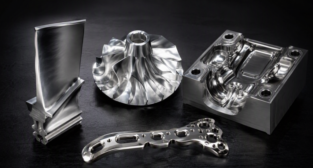
What 5-axis is for: turbine blades, impellers, medical implants, and complex mold cavities
5. Precautions: What Actually Goes Wrong
When choosing and specifying:
- 1. Don’t buy axes you don’t need. Specifying simultaneous 5-axis for a part that is really “flat faces at angles” is the most common waste in machining procurement — 3+2 positional machining does it stiffer, faster to program, and cheaper. Only continuously curved surfaces genuinely need simultaneous motion.
- 2. Don’t force complex parts onto 3-axis to save the hourly rate. Five manual setups at $80–150 of labor each, plus 18% scrap risk, routinely costs more than one 5-axis setup. Compare total cost per accepted part, never the machine rate.
- 3. Count setups at the quote stage. Rule of thumb: if a part needs more than 2 setups on 3-axis, get a 5-axis comparison quote.
- 4. Tolerance drives the decision as much as geometry. If critical features live on different faces with tight positional relationships (true position ±0.05 mm or better), single-setup machining is the safe route.
For 5-axis work specifically:
- 5. Programming is the real bottleneck. Simultaneous 5-axis toolpaths demand advanced CAM, full machine simulation, and collision checking — a gouged impeller or a crashed spindle costs far more than programming time. Ask your supplier how toolpaths are verified.
- 6. Rotary axis calibration matters. The accuracy of a 5-axis part lives or dies on the geometric calibration of the rotary axes (pivot points, squareness). Reputable shops verify with ball-bar tests and in-process probing — ask.
- 7. Workholding becomes the weak link. Single-setup machining concentrates all clamping into one fixture; it must be rigid, provide tool clearance from five directions, and not distort thin walls.
- 8. Shorter tools are a hidden benefit — use them. Tilting the part instead of reaching with a long tool improves rigidity, surface finish, and tool life; a good 5-axis programmer exploits this deliberately.
Universal:
- 9. Axis count never rescues bad workholding, dull tools, or poor thermal control — the fundamentals still decide the final micrometers.
- 10. Verify with datum-referenced inspection. Multi-face parts should come with CMM reports tying all critical features back to one datum scheme; that’s the proof the single-setup advantage was actually delivered.
6. Quick Decision Guide
| Your part looks like… | Choose |
| A plate with pockets and holes | 3 ejes |
| Features on 2–3 sides, tolerances ≥ ±0.1 mm | 3-axis (multi-setup) |
| Cylinder with cross-holes / flats / helical features | 4 ejes |
| Box with features on 4+ sides, moderate complexity | 4-axis or 3+2 |
| Angled holes / faces on multiple planes | 3+2 positional 5-axis |
| Impeller, blade, organic sculpted surface | Simultaneous 5-axis |
| Tight feature-to-feature GD&T across faces | 5-axis single setup |
| 500+ simple parts at lowest unit cost | 3 ejes |
The Right Machine for the Geometry
At Utely Machine, we run 3-axis, 4-axis, and 5-axis (3+2 and simultaneous) machining centers — so the recommendation follows your part, not our machine schedule. Upload your STEP file for a free DFM review and 24-hour quotation: we’ll tell you honestly which configuration your geometry and tolerances actually need, with CMM inspection reports on every critical dimension. Visit us at www.utelymachine.com.