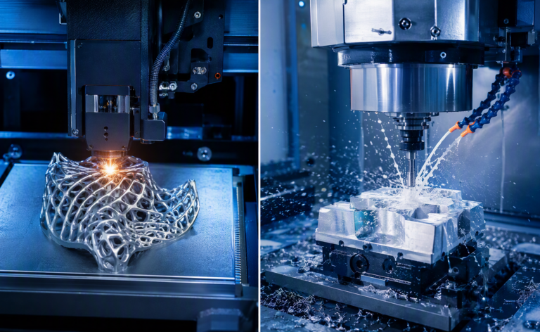


CNC Machining Aluminum Heat Sinks: Slot Depth, Accuracy, Applications
Complete design freedom from solid billet — but the slots between the fins set hard limits. Here is what depth does to accuracy, cost, and tool life.
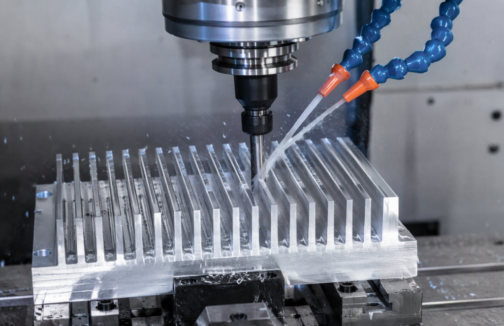
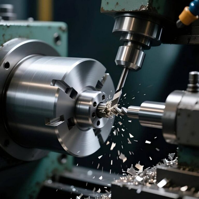
CNC milling an aluminum heat sink from a solid 6061 billet — the end mill works between rows of tall, thin fins.
When an extruded heat sink can’t deliver the geometry, the precision, or the integration your thermal design needs, CNC machining takes over.
Cutting a heat sink from a solid block of 6061-T6 or 6063 aluminum gives you complete design freedom — non-constant cross-sections, multi-directional fins, integrated mounting holes, threaded interfaces, and precision cavities in a single setup. But that freedom has hard limits, and most of them come down to one question: how deep and how narrow can the slots between fins realistically be cut? This guide covers what CNC machining can and cannot do for aluminum heat sinks, the accuracy you can hold at different slot depths, where machined heat sinks earn their cost, and the design mistakes that quietly double your quote.
1. Why Machine a Heat Sink Instead of Extruding One?
Extrusion is cheap at volume, but it locks you into a constant cross-section, limited fin aspect ratios, and a separate machining step for every hole or pocket. CNC machining from solid billet changes the equation:
- Geometry freedom — pin fins, cross-cut fins, stepped heights, curved fin fields, and multi-directional fins that no extrusion die can produce.
- One-piece integration — mounting holes, precision threads, component pockets, and cable channels machined in the same setup, with true positional accuracy between thermal and mechanical features.
- Zero tooling cost — no extrusion die NRE; the design is purely digital, ideal for prototypes and low-to-mid volumes.
- Material integrity — a monolithic base-to-fin thermal path with no bonded or brazed interface resistance.
- Tighter tolerances — ±0.05 mm is routine; ±0.003 mm is achievable on critical interfaces with the right shop.
The trade-off is cycle time and cost: every cubic millimeter of fin channel is removed by a rotating cutter, one pass at a time.
2. Fin and Slot Geometry: The Rules That Decide Your Quote
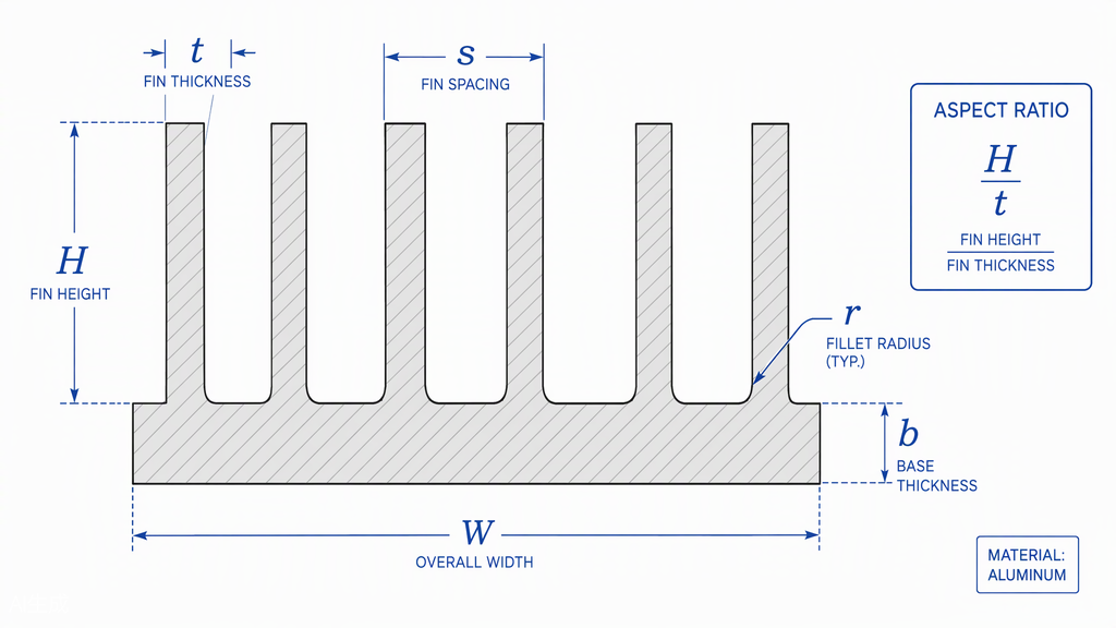
The geometry that governs manufacturability: fin thickness t, spacing s, height H, base thickness b, and the fillet radius at the fin root.
Heat sink performance scales with surface area — but CNC imposes strict geometric limits on how that area can be created. The controlling parameters:
| Parameter | Aluminum (CNC) Guideline | Why It Matters |
| Minimum fin thickness | ≥ 0.8–1.0 mm | Thinner fins vibrate under the cutter, taper, or break |
| Minimum slot width between fins | ≥ 1.5 mm | The end mill must physically fit; narrower needs fragile micro tools |
| Maximum aspect ratio (fin height ÷ thickness) | ≤ 6:1 standard; 10:1 practical ceiling | Beyond this, tool deflection and fin chatter destroy accuracy |
| Pocket / cavity depth | ≤ 4× tool diameter | Deeper pockets force long, flexible tool extensions |
| Fillet at fin base | 0.5 mm radius typical | Lets the cutter clear the corner; reduces stress concentration |
| Base flatness (contact surface) | ≤ ±0.05 mm; 0.01 mm achievable | Air gaps at the thermal interface can cut heat transfer by up to 50% |
| Mounting hole position | ≤ ±0.02 mm | Even clamping pressure across the TIM interface |
| Thread depth consistency | ≤ ±0.1 mm | Reliable fastener preload |
The aspect ratio is the single biggest cost driver. Staying within 6:1 for aluminum keeps tools short, rigid, and fast. Pushing toward 10:1 is possible — a 1 mm fin can reach 10 mm tall — but requires longer, slender end mills running at slower feeds with more passes, and the price curve turns steep.
3. Slot Depth: What Actually Happens as the Cut Gets Deeper
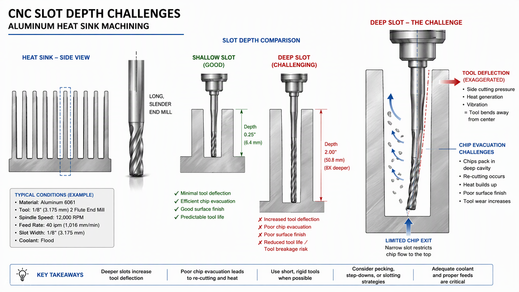
Shallow slot vs. deep slot: as depth grows, tool deflection, chip packing, and heat build-up compound.
The slots between fins are where heat sink machining is won or lost. As slot depth increases relative to width, four problems compound:
- 1. Tool deflection. A deep, narrow slot demands a small-diameter end mill with a long reach. Side cutting pressure bends the cutter away from center — the result is tapered slot walls (wider at the top than the bottom), dimensional error, and in the worst case a snapped tool buried in the part.
- 2. Chip evacuation. Chips pack into the deep cavity and get re-cut, scratching slot floors, generating heat, and accelerating tool wear. Coolant struggles to reach the cutting edge at depth.
- 3. Chatter and surface finish. Long, flexible tools vibrate; the fin walls pick up chatter marks that no downstream process removes economically.
- 4. Cycle time. Depth is removed in layers. At 0.05 mm depth per pass, a 1 mm fin spacing with 25 mm fin height means hundreds of controlled passes. Halve the fin spacing and the pass count roughly doubles — and so does the machining time.
Practical accuracy expectations by slot depth (6061-T6 aluminum):
| Slot / Fin Condition | Realistic Accuracy |
| Shallow slots (depth < 15 mm, width ≥ 2 mm, standard end mills) | ±0.05 mm on width and position; clean vertical walls |
| Medium depth (15–25 mm, standard tool lengths) | ±0.1 mm; slight taper possible — verify wall parallelism if the slot guides a component |
| Deep narrow slots (> 25 mm, or aspect ratio approaching 10:1) | ±0.15–0.25 mm with specialty tooling; expect chatter risk, slower feeds, and higher cost |
| Mounting surface (fly-cut / face-milled finish pass) | Flatness ≤ 0.01–0.05 mm; Ra 0.8–1.6 µm with sharp polished-flute tooling |
Two design notes that save real money: square slot ends are impossible — a rotating cutter naturally leaves semicircular ends (radius = half the slot width), so design for them or add dog-bone reliefs; and every internal vertical corner needs a radius — perfectly sharp internal corners require EDM at a very different price point.
4. The Contact Surface: Where Accuracy Pays for Itself
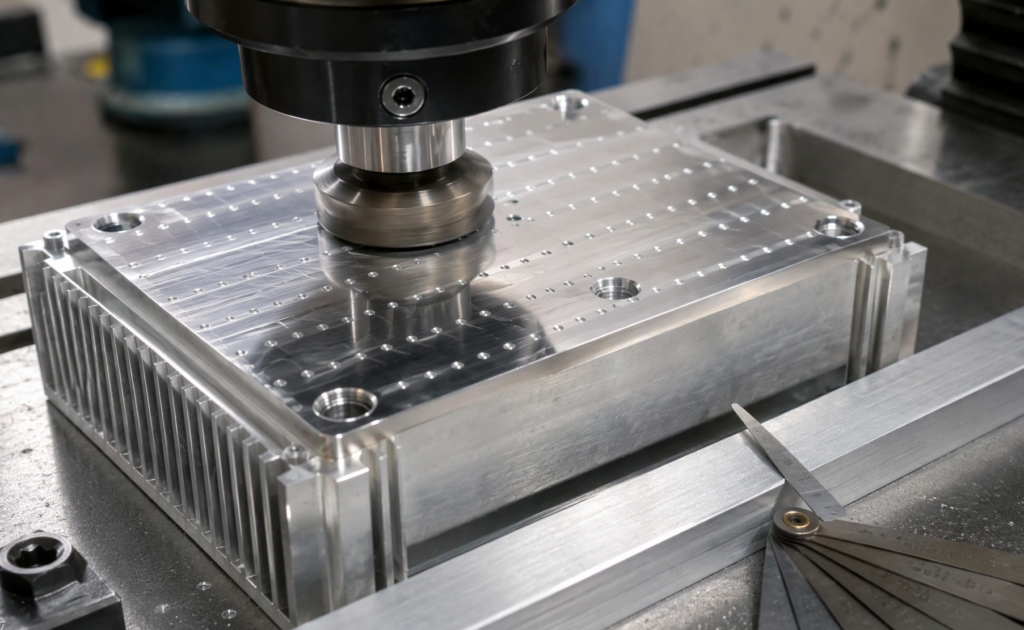
Face-milling the heat sink base to a mirror-flat finish — flatness is verified with straightedge and feeler gauge.
The fins dump heat to the air, but the base contact surface is where heat enters the heat sink — and it is the most important surface on the part. A non-flat base creates air gaps between the component and the heat sink, and air is an excellent insulator: poor interface contact can reduce effective heat transfer by up to 50%.
Specifications that protect thermal performance:
- Contact surface flatness: ≤ ±0.05 mm (0.01 mm achievable with a dedicated finish pass) across the full contact area
- Surface finish: Ra 0.8–1.6 µm on the mounting face — a fly-cutter or face-mill pass at high RPM and slow feed; fins can stay at standard as-machined Ra 3.2 µm
- Mounting hole position ≤ ±0.02 mm so clamping pressure spreads evenly across the thermal interface material
One frequently missed detail: anodizing adds 5–25 µm of oxide layer. It improves corrosion resistance and slightly boosts radiative emissivity (especially black anodizing), but it marginally hurts conduction at the contact interface. Best practice: mask the mounting surface during anodizing and state on the drawing whether dimensions apply before or after coating.
5. Applications: Where Machined Aluminum Heat Sinks Earn Their Cost
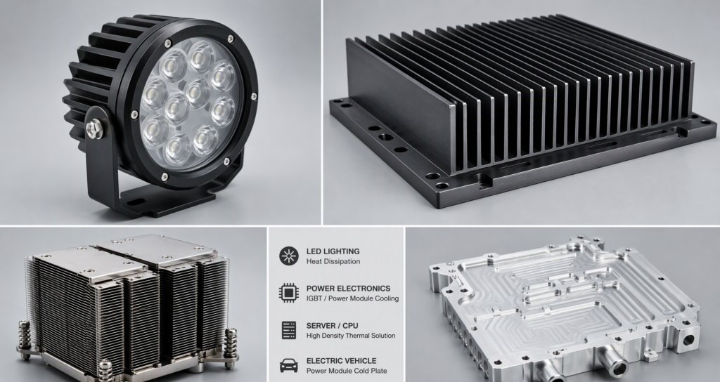
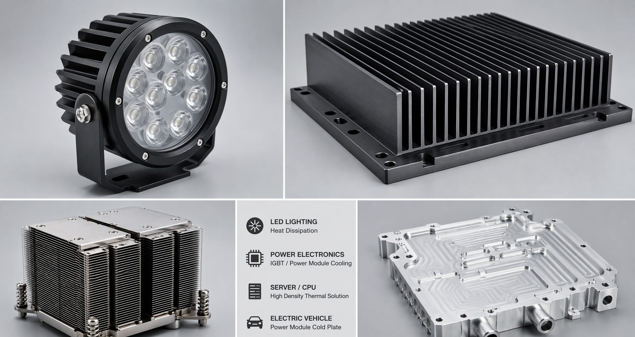
Machined aluminum heat sinks at work: LED lighting, IGBT power electronics, server CPUs, and EV power module cold plates.
- LED lighting — integrated heat sink housings where the fixture body is the thermal path; fin geometry, cosmetic anodizing, and threaded mounting in one part. A documented case: redesigning fin height and spacing (not fin count) brought LED junction temperature 18% below the rated limit, passing thermal testing on the first iteration.
- Power electronics (IGBT / MOSFET modules) — base flatness and mounting-hole position directly control thermal interface quality; CNC holds both in one setup.
- Servers, CPUs / GPUs, and data centers — dense fin fields and complex footprints that exceed extrusion capability; hybrid skived-fin + CNC-finished designs are common.
- EV and automotive power modules — cold plates and heat sinks with integrated coolant channels, sealed grooves, and mounting interfaces.
- RF, telecom, and 5G infrastructure — enclosure-integrated heat sinks where shielding, mounting, and cooling merge into one machined housing.
- Aerospace and medical imaging — low volumes, complex geometry, and verified precision: exactly CNC’s home ground.
When to choose alternatives: high-volume constant-section profiles → extrusion; ultra-thin dense fins (down to 0.1–0.2 mm, aspect ratios past 40:1) → skived fin; very large assemblies → bonded fin. CNC machining owns the space where geometry, integration, and precision matter more than piece price.
6. Precautions: The Design Mistakes That Cost You
- 1. Respect the 6:1 aspect ratio. Overdesigning fins too thin or too tall inflates tool deflection, machining time, and your quote — often for little thermal gain. If thermal simulation demands more area, consider a hybrid extrusion / skiving + CNC-finish design.
- 2. Keep slots ≥ 1.5 mm wide and pockets ≤ 4× tool diameter deep. Narrower and deeper means specialty micro tools, slower feeds, and real breakage risk.
- 3. Radius every internal corner and fin root (0.5 mm typical). Sharp internal corners mean EDM — and a different price bracket.
- 4. Design semicircular slot ends. If a mating tab must reach the slot end, add reliefs — never call out a zero-radius internal corner without saying how it will be made.
- 5. Tolerance only what the function needs. Tightening 0.05 mm to 0.01 mm roughly follows an exponential cost curve. Keep tight callouts on the contact surface, hole pattern, and threads; let fins run at standard machining tolerance.
- 6. Specify base flatness and finish explicitly — and mask the contact surface during anodizing. State whether dimensions apply pre- or post-coating.
- 7. Choose the right alloy. 6061-T6 for strength and machinability; 6063-T5 for the best surface finish and anodizing response; both deliver 167–200 W/m·K thermal conductivity.
- 8. Deburr and clean before finishing. Fin tips and slot floors trap burrs; burrs on the contact face defeat the flatness you paid for.
- 9. Beware batch variation. Different aluminum batches vary slightly in hardness; good shops run first-piece inspection and test cuts before the full run.
- 10. Ask for a DFM review before freezing the design. A good fabricator flags un-machinable features, over-tight tolerances, and cost drivers — before they become scrap.
Get Your Heat Sink Machined Right
At Utely Machine, we machine custom aluminum heat sinks from solid 6061/6063 billet — fin fields, precision contact surfaces, integrated mounting and threads, anodizing and finishing under one roof, with CMM-verified flatness and hole position on every critical interface. Upload your STEP file for a free DFM review and 24-hour quotation: we’ll tell you honestly whether your fin geometry machines economically, and what to change if it doesn’t. Visit us at www.utelymachine.com.