


3D Printing vs. CNC Machining: Differences, Applications, and How to Choose the Right Process
Additive or subtractive? Two tools with opposite strengths — and a practical framework for knowing exactly when to use which.
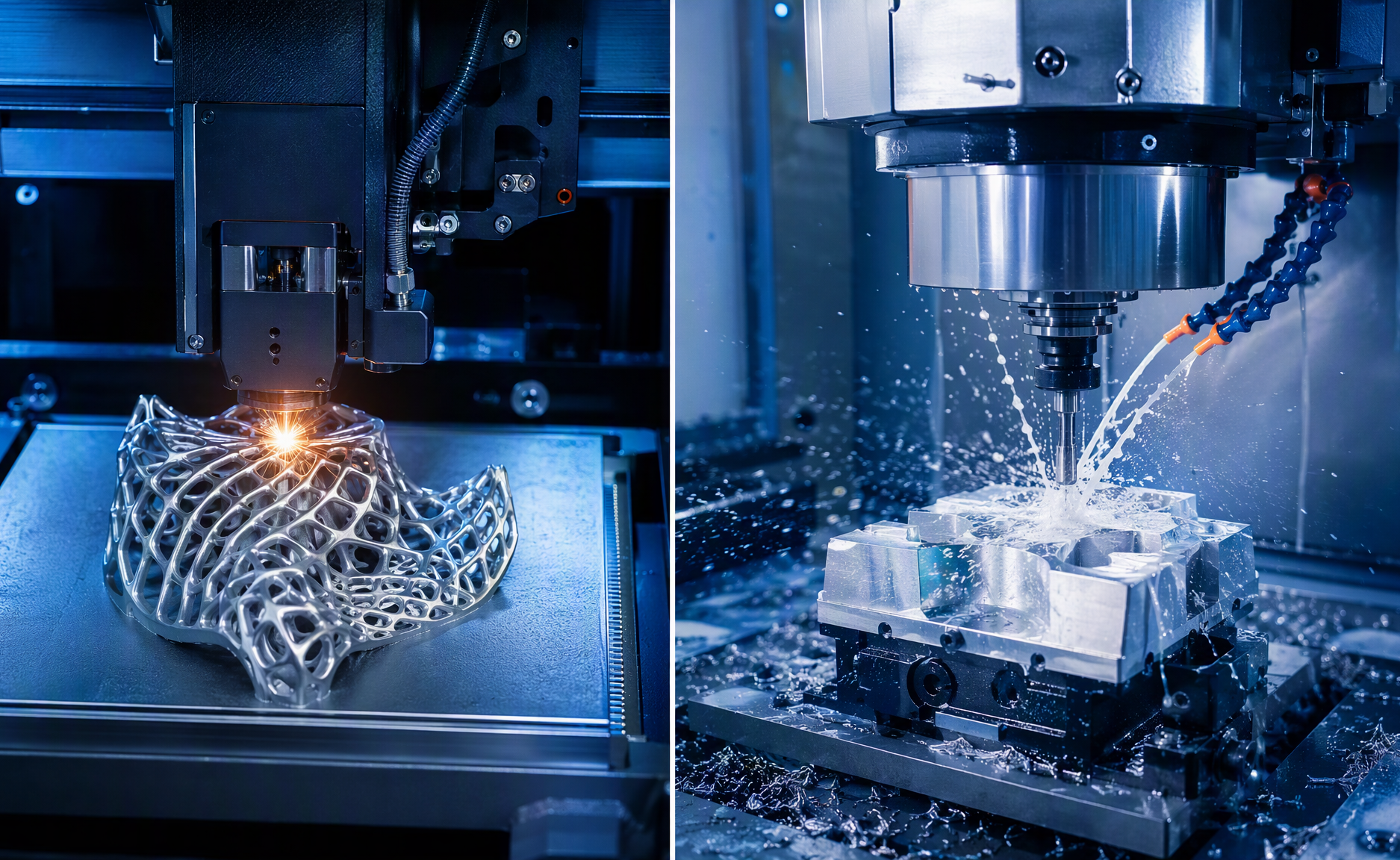
Two worlds of manufacturing: a laser-built lattice part on the left, a 5-axis CNC mill cutting aluminum on the right.
Additive or subtractive? It’s one of the first questions in any hardware project — and one of the most commonly misunderstood. 3D printing builds parts layer by layer from nothing; CNC machining carves them from solid stock. Neither is “the future” replacing the other.
They are two tools with opposite strengths, and the shops that win are the ones that know exactly when to use which. This guide breaks down the real differences, the applications each owns, the honest pros and cons, and a practical decision framework.
1. The Fundamental Difference: Add Up vs. Cut Away
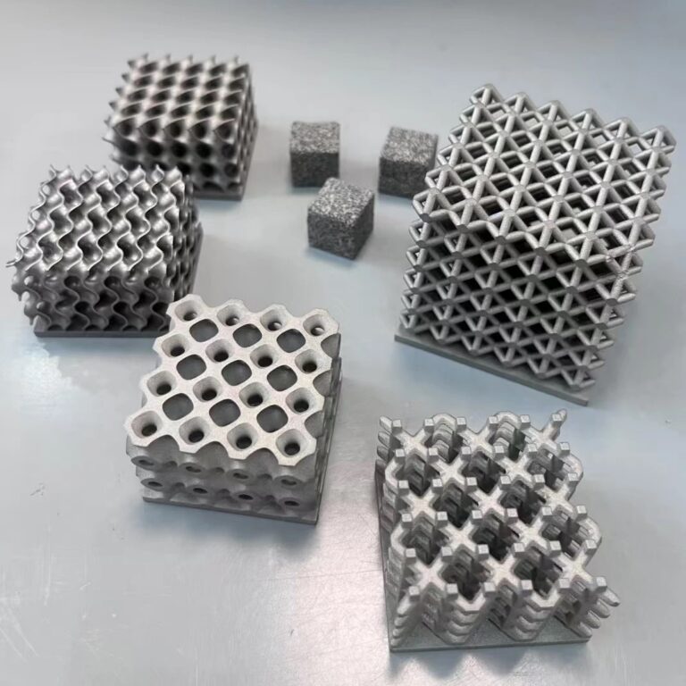
3D printing (additive manufacturing) starts with an empty build platform and adds material only where the part needs it — extruded filament (FDM), cured resin (SLA), sintered nylon powder (SLS/MJF), or laser-melted metal powder (SLM/DMLS). Complexity is nearly free: the machine doesn’t care whether it’s printing a cube or a topology-optimized lattice.
CNC machining (subtractive manufacturing) starts with a solid block and removes everything that isn’t the part, using computer-controlled mills, lathes, and drills. The cutting tool must physically reach every surface it creates — which defines both its precision and its limits.
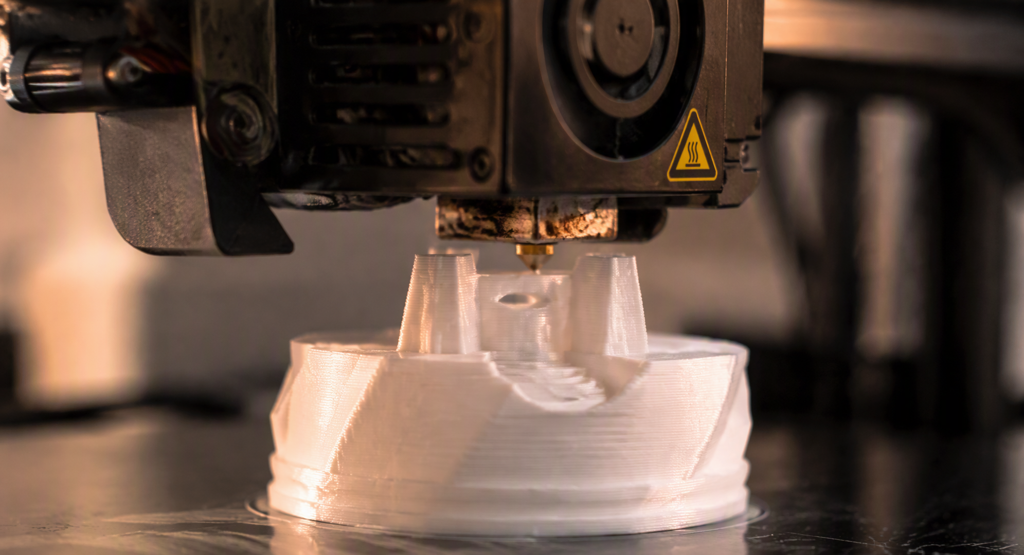
Additive manufacturing: an FDM nozzle laying down molten filament, one layer at a time.
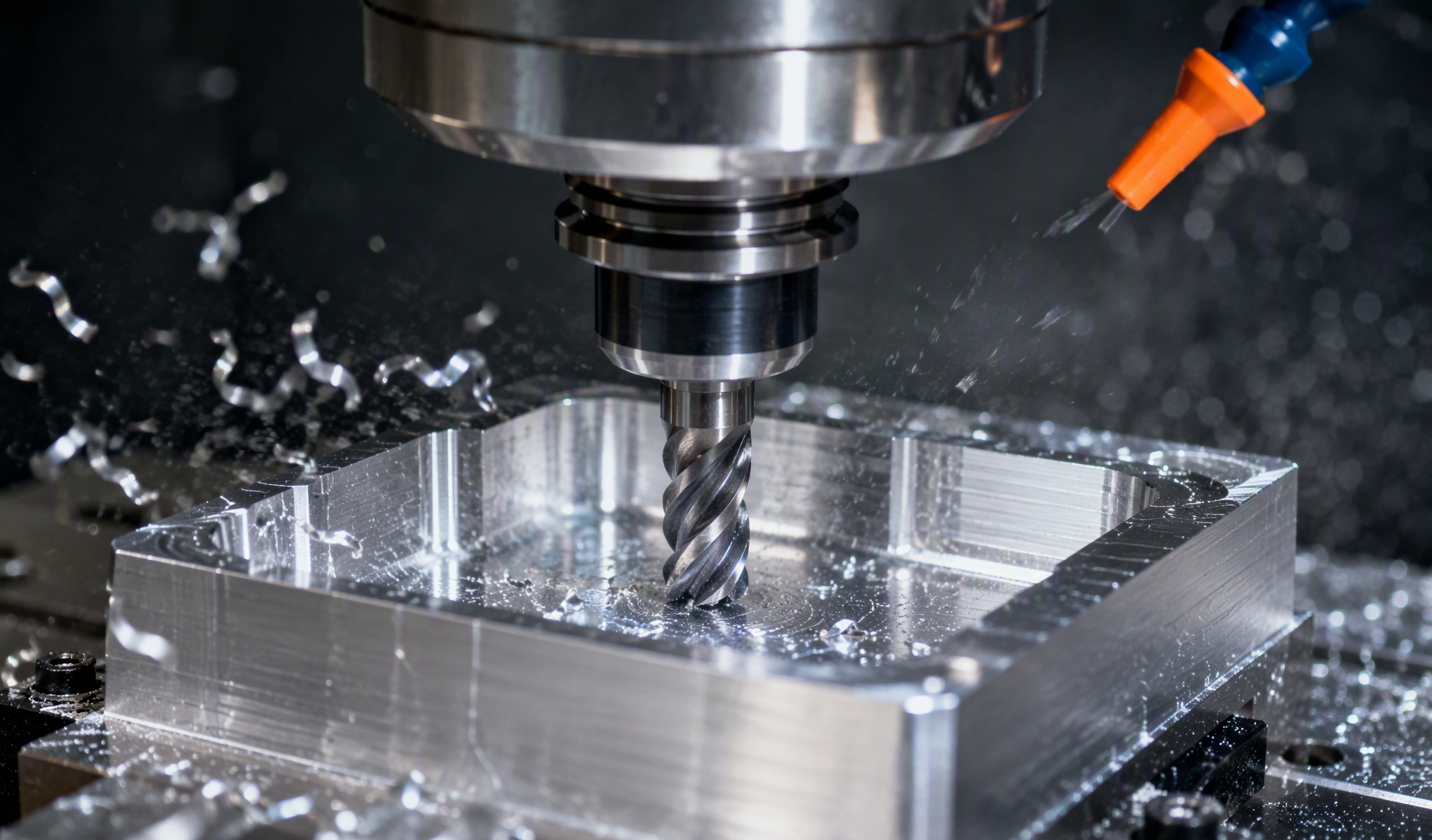
Subtractive manufacturing: a CNC end mill carving a precise pocket from a solid aluminum block.
2. Head-to-Head Comparison
| Factor | 3D Printing (Additive) | CNC Machining (Subtractive) |
| Material approach | Adds material layer by layer | Removes material from solid stock |
| Material waste | Low (5–10%, supports only) | High (30–70% becomes chips) |
| Typical tolerance | ±0.1–0.5 mm (best: ±0.025–0.05 mm) | ±0.005–0.025 mm routinely |
| Surface finish (as-made) | Ra 8–25 μm, visible layer lines | Ra 1.6–3.2 μm standard; 0.4–0.8 μm fine |
| Geometric complexity | Nearly unlimited — internal channels, lattices, undercuts | Limited by tool access; internal corners stay radiused |
| Material range | Growing but limited (specific printable alloys/plastics) | Very broad — virtually any metal, plastic, wood |
| Material properties | Often anisotropic; may not match wrought stock | Full native properties of the source material |
| Setup cost | Near zero — load a file and print | CAM programming, fixturing, workholding |
| Cost at 1–50 pcs | Usually cheaper | Higher (setup dominates) |
| Cost at 500+ pcs | Flat — every part costs the same | Drops steeply as setup amortizes |
| Design-change cost | Free — send a new file | Reprogramming, possible new fixtures |
The cost crossover is revealing: for a medium-complexity aluminum bracket, industry pricing references show 3D printing winning at 1–50 units, CNC taking over somewhere between 50 and 500 units — with the exact break-even shifting toward printing as geometry gets more complex, and toward machining as tolerances get tighter.
3. 3D Printing: Strengths and Weaknesses
Where 3D printing wins
- Geometric freedom. Internal cooling channels that snake through a part, weight-saving lattices, organic topology-optimized shapes, assemblies consolidated into one printed piece — geometry no cutting tool can reach.
- Speed to first part. No programming, no fixtures, no tooling. From CAD to physical part in 24–48 hours, and design iteration costs nothing but machine time.
- Material efficiency. Printing uses roughly what the part weighs. When the raw material is titanium at $100+/kg, avoiding 70% chip waste is a serious cost argument.
- Low-volume economics. Per-part cost is flat, making 1–100 units of complex parts dramatically cheaper than machining.
- Part consolidation. Five machined parts that bolted together become one printed part — fewer fasteners, fewer failure points, less assembly labor.
Where 3D printing struggles
- Precision and finish. Layer lines, stepped surfaces, and looser tolerances mean critical fits usually need secondary machining.
- Anisotropic strength. Layer-by-layer construction creates weak directions; FFF parts can retain as little as 10% of native material strength, and even metal AM needs heat treatment to approach wrought properties.
- Material menu. You print the alloys and polymers the process supports — not any certified wrought grade your specification calls for.
- No volume discount. The 1,000th part costs the same as the first. Scale economics belong to subtractive.
4. CNC Machining: Strengths and Weaknesses
Where CNC machining wins
- Precision. Tolerances of ±0.005–0.025 mm are routine — the gold standard. Sealing faces, bearing bores, threads, and mating features come off the machine ready to assemble.
- Surface finish. Ra 1.6–3.2 μm straight off the tool; fine finishing passes reach mirror quality without post-processing.
- Real materials, full properties. The part is the certified wrought or cast alloy — 6061-T6 behaves exactly like 6061-T6, with isotropic strength and full fatigue performance.
- Material breadth. Metals, engineering plastics, wood, composites — if it can be fixtured, it can be cut.
- Scale economics. Once programmed and fixtured, repeat orders are fast and unit costs fall sharply with volume. Above a few hundred parts, machining usually wins on price.
Where CNC machining struggles
- Tool access physics. A cutter needs a straight path to every surface. Deep internal channels, enclosed cavities, and sharp internal corners are impossible or require splitting the part.
- Material waste. A 1 kg part may start as a 5 kg billet — 4 kg of chips. On expensive alloys, that waste is real money.
- Setup overhead. CAM programming, custom fixtures, and workholding design take time and skilled labor before the first chip flies.
- Design-change friction. A revised model can mean reprogramming toolpaths and reworking fixtures — iteration is slower and costlier than re-slicing a print file.
5. Applications: Which Process Owns Which Territory
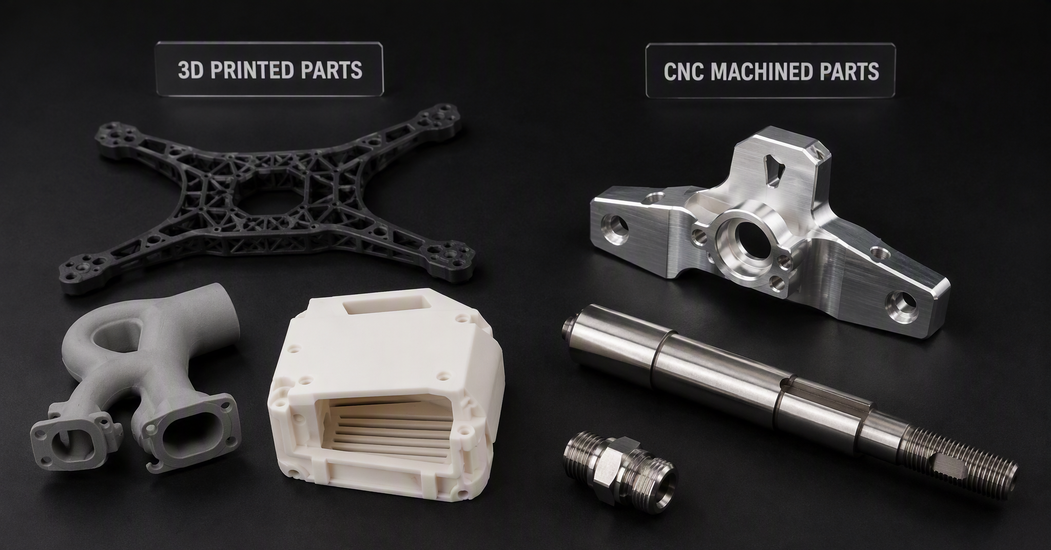
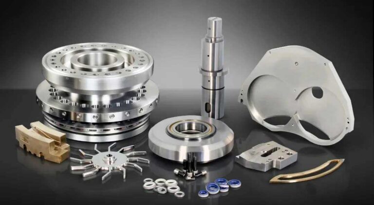
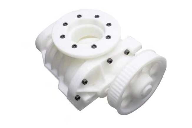
Which parts belong to which process: printed lattices, manifolds and enclosures on the left; machined brackets, shafts and precision fittings on the right.
Choose 3D printing for:
- Rapid prototypes and design iterations (concept models, fit checks, functional tests)
- Complex internal geometry — conformal cooling channels, fluid manifolds, heat exchangers
- Lightweight topology-optimized brackets and lattice structures
- Low-volume production of complex parts (1–100 units)
- Part consolidation — replacing assemblies with single printed components
- Difficult-to-machine materials (titanium, Inconel) where chip waste hurts
- Custom and one-off parts — jigs, fixtures, medical models, legacy spares
Choose CNC machining for:
- Precision functional parts — bearing seats, threads, sealing surfaces, tight-tolerance fits
- Structural and load-bearing parts needing full, certified material properties
- Medium-to-high volume production (hundreds to thousands)
- Simple-to-moderate prismatic geometry (brackets, housings, plates, shafts)
- Parts requiring specific certified alloys or engineering plastics
- Mirror finishes and cosmetic surfaces without post-processing
6. The Hybrid Sweet Spot
Here’s what experienced manufacturers know: the best answer is often both. Print the complex near-net-shape geometry — internal channels, lattices, organic forms — then CNC-machine the critical features: bores, threads, sealing faces, and mating surfaces that demand ±0.02 mm.
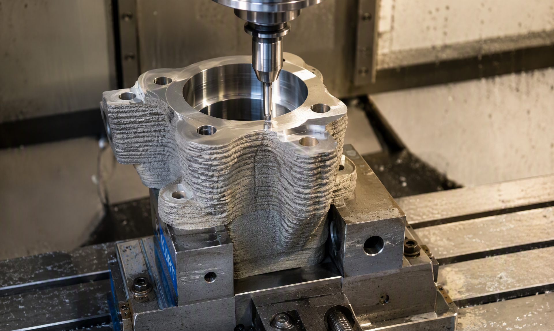
Hybrid manufacturing: a rough 3D-printed part in a CNC vise, its critical bore being finished to mirror smoothness.
This hybrid workflow is now standard practice for aerospace brackets, medical implants, and performance automotive parts — additive contributes the geometry, subtractive contributes the precision, and the part gets the best of both.
7. Quick Decision Framework
- 1. Tolerance tighter than ±0.02 mm? → CNC
- 2. Internal channels, lattices, or undercuts? → 3D printing
- 3. Volume above ~500 units, simple geometry? → CNC
- 4. Prototype or design still changing? → 3D printing
- 5. Surface finish below Ra 3.2 μm needed directly? → CNC
- 6. Certified wrought material properties required? → CNC
- 7. Complex geometry and precision features? → Hybrid: print, then machine
8. Conclusion
3D printing and CNC machining aren’t competitors — they’re complements. Printing buys you geometry, speed, and zero tooling; machining buys you precision, certified materials, and scale economics. The wrong question is “which is better?” The right question is “which process does this feature need?” — and increasingly, the answer is a workflow that uses both in sequence.
Not sure which process fits your part? At Utely Machine (www.utelymachine.com), we run both worlds under one roof — industrial 3D printing (FDM, SLA, SLS, SLM metal) and precision CNC machining (3/4/5-axis milling, turning, EDM) — with hybrid print-then-machine workflows as a standard offering. Send us your STEP file for a free DFM review and a 24-hour quotation, and our engineers will recommend the most cost-effective route for your geometry, tolerances, and volume.