


Machining Carbon Fiber (CFRP): Advantages, Disadvantages, Applications, and the Precautions That Separate Good Parts from Scrap
The same properties that make CFRP extraordinary in service make it one of the most demanding materials to machine.
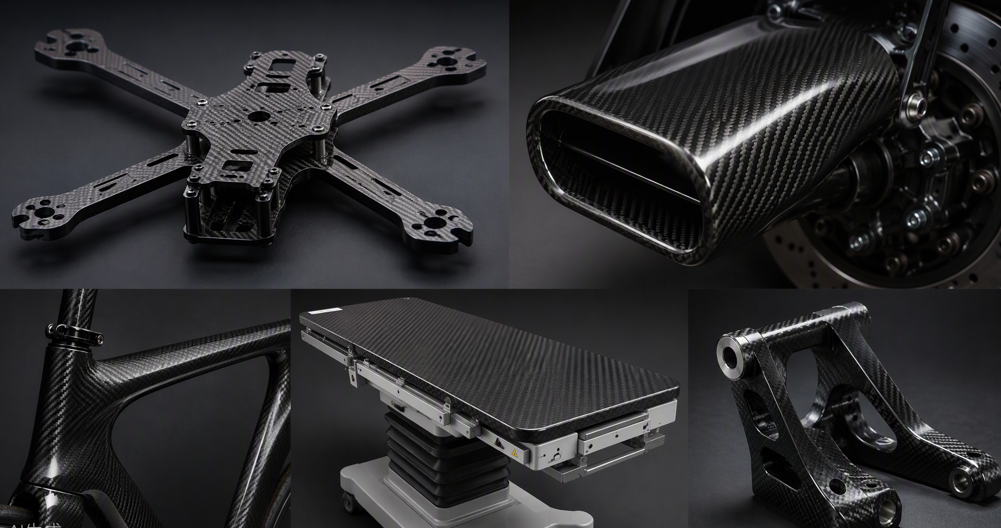
Precision CNC machined CFRP parts: drone frame, brackets and profiled panels in 2×2 twill weave.
Carbon fiber reinforced polymer (CFRP) is the material that lets a racing drone survive crashes, a superbike shed kilograms, and an X-ray table stay invisible to radiation.
But the same properties that make it extraordinary in service — extreme stiffness, abrasive fibers, a layered anisotropic structure — make it one of the most demanding materials to machine. Cut it wrong and you get delaminated edges, frayed fibers, burned resin, and a workshop full of conductive dust. Cut it right and you get parts with ±0.02 mm profiles that no metal can match gram-for-gram. This guide covers the honest advantages and disadvantages of carbon fiber, where machined CFRP parts earn their cost, and the workshop precautions that decide success or scrap.
1. Why Machine Carbon Fiber at All? The Advantages
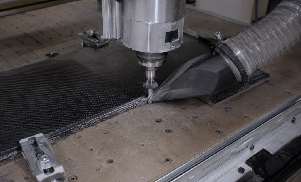
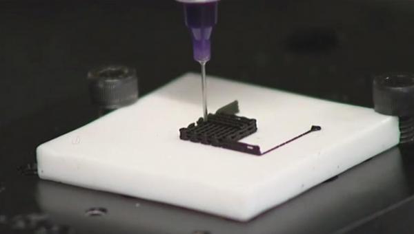
Routing a carbon fiber sheet: diamond-coated tooling and point-of-cut dust extraction working together.
CFRP parts are typically laid up and cured near net shape — but almost every finished part still needs machining: edge trimming, drilled fastener holes, pockets, slots, and profile finishing. The material’s in-service advantages are what make that effort worthwhile:
- Unbeatable strength-to-weight ratio: at equal stiffness, a CFRP part weighs a fraction of its aluminum equivalent — the core reason aerospace, UAV, and motorsport engineering runs on carbon.
- High fatigue strength: CFRP outlasts metal alloys under cyclic loading — why it is replacing metals in medical devices and robotics arms.
- Corrosion and chemical immunity: no rust, no oxidation; resistant to most acids, alkalis, solvents, and salts.
- Radiolucency: transparent to X-rays — irreplaceable for medical imaging tables and device housings.
- Low thermal expansion and vibration damping: dimensionally stable across temperature swings, and quieter, more stable structures than metals.
And machining itself brings advantages over molded-only production: no mold cost for one-off or low-volume parts, design changes are a CAD edit away, and a 3K twill plate can become a finished drone frame in a single setup.
2. The Honest Disadvantages
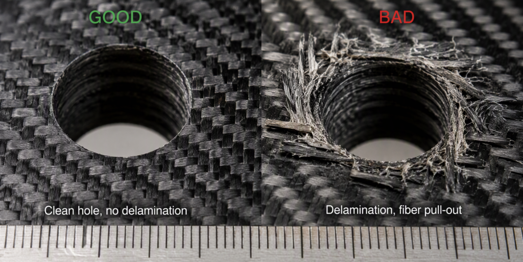
The difference process control makes: a clean drilled hole versus delamination and fiber pull-out.
2.1 Machining challenges (process-level)
- Extreme tool wear: carbon fibers are highly abrasive — flank wear beyond 0.3 mm can occur after short cutting lengths with ordinary carbide. Diamond-coated (CVD) or PCD tooling is not optional; it’s the entry ticket.
- Delamination: the #1 defect. Layers separate at hole entry/exit or trimmed edges when cutting forces get too high — destroying structural integrity and fatigue life.
- Fiber pull-out and fraying: especially when cutting across the fiber direction (0° ply orientation is the worst case for tool wear).
- Heat damage: the resin matrix conducts heat poorly (0.5–1.0 W/m·K), so cutting heat concentrates at the edge — degrading the matrix and accelerating tool wear. Flood coolant is often unusable on laminates, so most CFRP machining runs dry with extraction.
- Burrs and matrix cracking: secondary deburring adds time and cost.
2.2 Material-level drawbacks
- Brittleness under impact: CFRP fails by cracking along fibers or fiber-matrix debonding, with little deformation before fracture — it does not bend like metal, it breaks.
- Cost: carbon fiber production is roughly 14× more energy-intensive than steel, and the material price reflects it.
- Inspection burden: internal damage can be invisible to the eye, so in-service inspection frequency is high.
- No established recycling: end-of-life parts are downcycled into short-fiber compounds or burned for energy recovery.
- Anisotropy is a design constraint: strength lives along the fibers; loads across them are carried by resin alone.
3. Where Machined Carbon Fiber Earns Its Keep: Applications
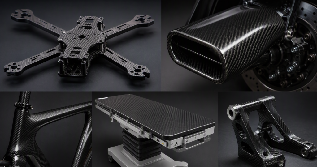
CFRP at work: UAV frames, automotive aero, cycling, medical imaging tables and aerospace brackets.
| Промышленность | Typical machined CFRP parts | Why carbon wins |
| Drones / UAV | Frames, arms, propellers, camera mounts | Stiffness at minimum weight = flight time; ±0.02 mm propeller profiles for aerodynamic efficiency |
| Аэрокосмическая промышленность | Brackets, interior panels, structural trims, satellite structures | Every gram costs fuel; fatigue and corrosion resistance |
| Automotive / motorsport | Aero trims, intake ducts, brackets, battery enclosures | Weight reduction where unsprung mass matters |
| Медицина | X-ray/CT table tops, device housings, surgical robot arms | Radiolucency + fatigue strength replacing metal alloys |
| Sports & consumer | Bicycle frames, rackets, tripod plates, audio components | Stiffness, damping, premium aesthetics |
| Industrial / robotics | Gripper arms, gantry plates, inspection fixtures | Low inertia, vibration damping, dimensional stability |
4. The Precautions: How to Machine CFRP Without Ruining It
4.1 Tooling and parameters
- Use diamond-coated (CVD) or PCD tools. Uncoated carbide dulls within meters of cutting; a worn tool raises cutting force, which directly increases delamination and dust.
- High speed, moderate feed: higher cutting speeds with lower feed rates minimize tool wear and heat input; a cutting speed around 55 m/min is a documented sweet spot for drilling quality vs. dust generation.
- Replace tools on schedule, not on failure — worn edges multiply respirable dust and delamination.
- Drill pilot holes before full-size holes; support the exit side with a backing board to prevent exit splintering.
- Respect fiber orientation: plan cuts along the fiber direction where possible; cross-fiber cuts fray and wear tools faster.
- Design for machining: internal corner radii of at least 3 mm; avoid sharp internal corners that force chatter and matrix cracking.
4.2 Fixturing and machine protection
- Rigid, stress-free clamping: thin CFRP panels vibrate and chatter if under-supported — chatter marks become delamination.
- Protect the machine: carbon dust is abrasive and electrically conductive — it wears bearings and ball screws, and can short circuit electronics. Sealed or air-purged enclosures, covered ways, and dust-proof electrics are mandatory.
- Vacuum at the point of cut: position extraction directly at the cutting zone, not just in the room.
4.3 Dust, health, and safety — the part nobody should skip
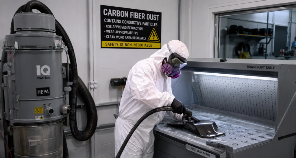
Full PPE, downdraft table and HEPA extraction — non-negotiable in a CFRP workshop.
- Particle size is the problem: machining generates particles down to 0.25–1 µm. Particles of 1–5 µm reach deep into the lungs; sub-1 µm particles can enter the alveoli and bloodstream. High-speed trimming produces 2–8× more dust.
- Extraction: HEPA filtration capturing ≥99.9% of particles ≥0.3 µm, at the source. Household vacuums are not acceptable — their motors can be shorted by conductive dust.
- PPE: respirator (not a paper mask), sealed goggles, gloves, and protective clothing with elastic cuffs; carbon splinters are sharp and irritating to skin.
- Housekeeping: frequent cleaning with air-ejector or industrial vacuums; never dry-sweep.
- Electrical safety: keep dust away from open electrical cabinets, outlets, and unprotected equipment — conductive carbon dust causes short circuits.
4.4 Finishing touches
- Seal cut edges with epoxy/resin to prevent fraying and moisture ingress.
- Wet-sand edges with fine grit (200+) where cosmetics matter; polish for gloss.
- Avoid aggressive countersinking — never countersink beyond ~70% of laminate thickness.
- Ream after drilling for tight hole tolerances (carbide reamers, ~half drilling speed).
5. Quick Reference: Do’s and Don’ts
| Do | Don’t |
| Diamond-coated or PCD tooling | Standard HSS or worn carbide tools |
| Point-of-cut HEPA extraction | Household vacuum or open-air cutting |
| Backing board under drill exits | Drill unsupported exits |
| High speed + moderate feed, dry | Flood coolant on thin laminates |
| Corner radii ≥ 3 mm in design | Sharp internal corners |
| Cut along fiber direction where possible | Ignore laminate layup when planning cuts |
| Respirator + goggles + gloves + suit | Paper mask and bare hands |
| Seal machined edges with epoxy | Leave raw edges exposed to moisture |
| Replace tools on a schedule | Run tools until edges fray |
6. Carbon Fiber, Machined Right
At Utely Machine, CFRP machining runs on dedicated tooling, rigid fixturing, and full point-of-cut HEPA extraction — from single drone-frame prototypes to batches of precision panels with documented inspection. Upload your STEP file or drawing for a free DFM review and 24-hour quotation, including fiber-orientation and edge-sealing recommendations. Visit us at www.utelymachine.com.