


Rapid Prototyping Methods Explained: Processes, Pros & Cons, and How to Choose the Right One
From 3D printing to rapid tooling — a practical, honest comparison of the five manufacturing methods that take your product from CAD to physical part.
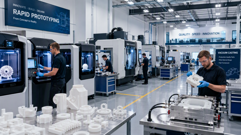
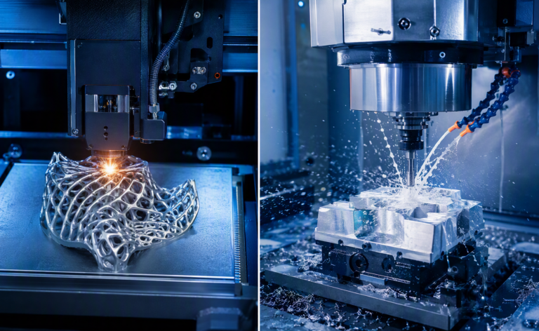
A modern rapid prototyping facility: industrial 3D printers, CNC machining centers and vacuum casting stations under one roof.
Bringing a new product from CAD model to physical part has never been faster — but “rapid prototyping” is not one single process. It is a family of manufacturing methods, each with its own strengths, limitations, and ideal batch size. Choose the wrong one and you waste budget and lead time; choose the right one and you validate your design in days instead of months.
In this guide, we break down the five most widely used rapid prototyping methods — 3D printing, CNC machining, vacuum casting, rapid injection molding, and sheet metal fabrication — with their working principles, process details, advantages, and disadvantages, so you can make a confident decision for your next project.
1. 3D Printing (Additive Manufacturing)
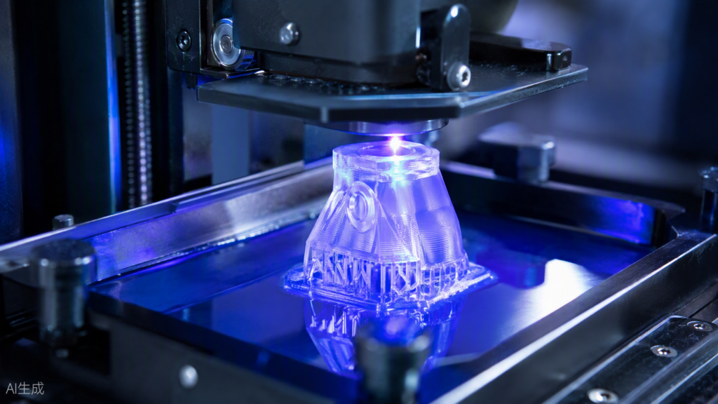
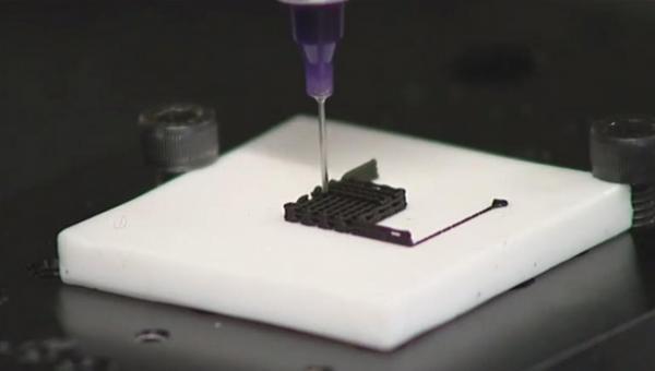
SLA 3D printing: a UV laser cures liquid photopolymer resin layer by layer into a translucent prototype.
How it works. 3D printing builds parts layer by layer directly from a CAD file, with no tooling required. The three mainstream technologies each serve a different purpose:
- FDM (Fused Deposition Modeling): thermoplastic filament (PLA, ABS, PETG) is melted and extruded through a nozzle. Lowest cost, ideal for early concept and size-check models.
- SLA (Stereolithography): a UV laser cures liquid photopolymer resin point by point. It delivers the smoothest surface and finest detail of any printing technology — perfect for appearance models and presentation prototypes.
- SLS (Selective Laser Sintering): a laser sinters nylon powder in a heated bed. Parts are strong, functional, and need no support structures — the go-to choice for functional testing, living hinges, and complex internal geometry.
Advantages
- Fastest turnaround: parts in hand within 1–3 days, sometimes hours
- No tooling or setup cost — extremely economical for one-off and very low volumes
- Unmatched design freedom: undercuts, lattice structures, internal channels, and hollow forms are all printable
- Iteration is nearly free: change the CAD file, print again
Disadvantages
- Material properties rarely match true production plastics; SLA resins can be brittle and UV-sensitive
- Visible layer lines on FDM and a slightly grainy finish on SLS often require sanding, polishing, or painting
- Anisotropic strength — parts are weaker along the layer direction
- Unit cost does not drop much with quantity, so it scales poorly beyond dozens of parts
2. CNC Machining (Subtractive Manufacturing)
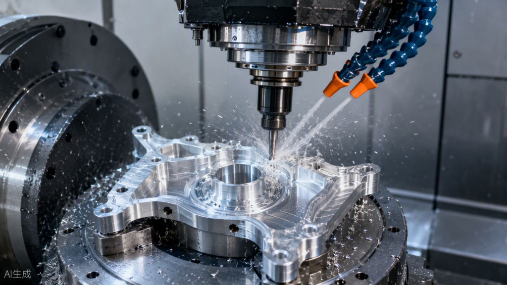
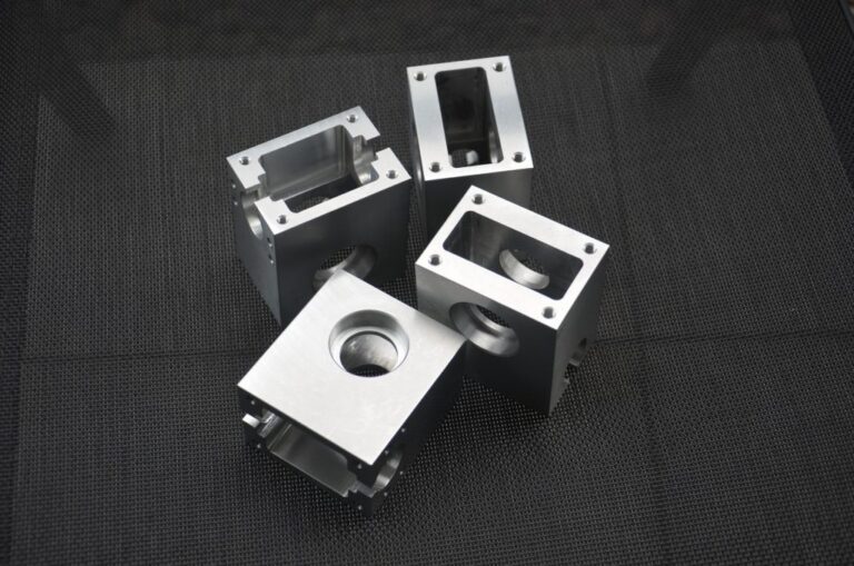
5-axis CNC machining: an end mill cuts an aluminum prototype with coolant flushing away chips.
How it works. CNC machining starts from a solid block of metal or engineering plastic and removes material with computer-controlled cutting tools. From 3-axis milling to 5-axis simultaneous machining, it handles everything from simple brackets to complex impellers and housings.
Advantages
- Uses real production materials — aluminum, stainless steel, brass, ABS, POM, PC, nylon — so mechanical and thermal test results are truly representative
- Tightest tolerances of any prototyping method, routinely ±0.05 mm or better
- Excellent as-machined surface finish, ideal for functional and precision-fit validation
- Great repeatability for small batches of 1–100 parts
Disadvantages
- Higher cost per part for complex geometries, especially when multiple setups or 5-axis work is needed
- Geometry is constrained by tool access — deep undercuts and enclosed internal channels can be impossible
- Subtractive process means material waste (chips), particularly costly in metals
- Programming and fixturing add lead time compared with pressing “print”
3. Vacuum Casting (Urethane / Silicone Mold Casting)
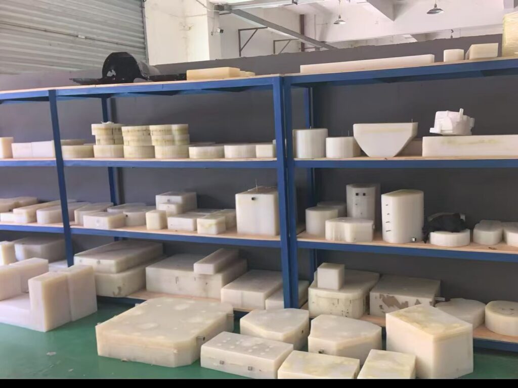
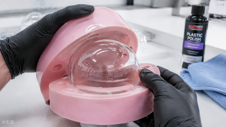
Vacuum casting: a technician opens a translucent silicone mold to release freshly cast polyurethane parts.
How it works. A master pattern — usually a high-quality SLA print or CNC-machined part — is suspended in a frame and liquid silicone is poured around it. Once cured, the silicone mold is cut open, the master removed, and polyurethane resin is cast into the cavity under vacuum to eliminate bubbles. One silicone mold typically yields 15–30 parts before it wears out.
Advantages
- The sweet spot for small batches of 10–100 parts: unit cost is a fraction of CNC or printing at this volume
- Surface quality and detail nearly indistinguishable from injection molding
- Wide choice of polyurethane resins that simulate ABS, PP, PC, rubber (Shore A elastomers), and even transparent or tinted parts
- Silicone tooling is ready in days, not weeks, and costs a small fraction of a steel mold
Disadvantages
- Requires a master pattern first — one more step in the chain
- Mold life is limited; not suitable for hundreds of parts or long production runs
- Cast urethanes have lower heat and chemical resistance than true engineering thermoplastics
- Process control matters: poor vacuum or mixing leads to bubbles and short shots
4. Rapid Injection Molding (Rapid Tooling)
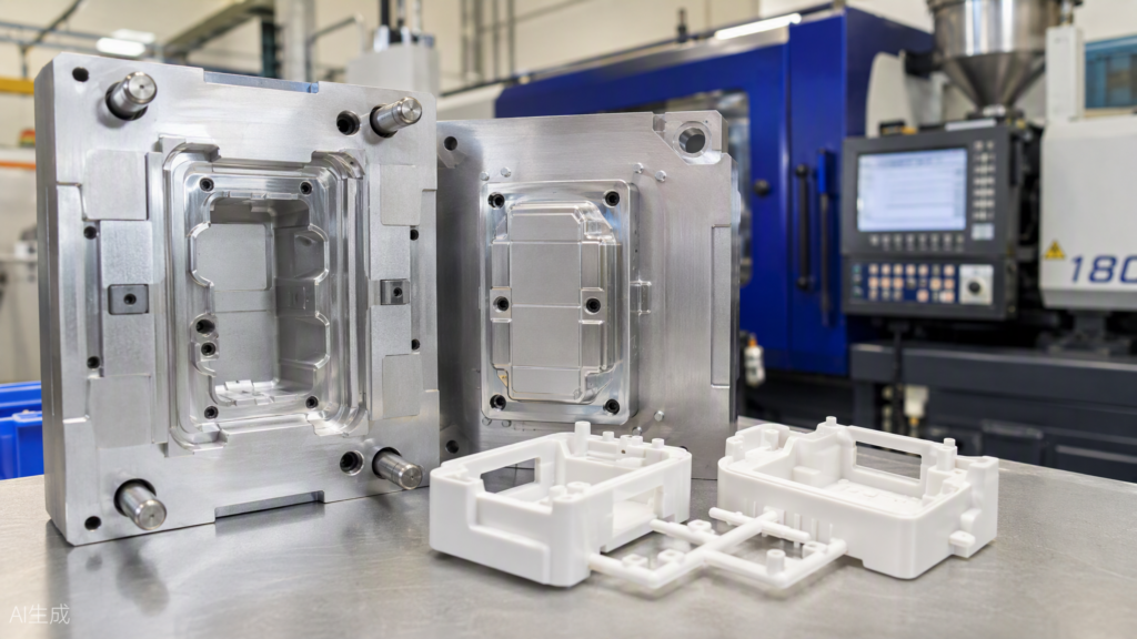
Rapid tooling: an open aluminum prototype mold with freshly molded plastic parts in front of an injection molding machine.
How it works. Instead of hardened production steel, rapid tooling uses aluminum or soft-steel molds machined quickly — often in 7–15 days. Real thermoplastic pellets (ABS, PC, PP, nylon…) are then injection molded exactly as in mass production, producing parts with true production-grade material properties.
Advantages
- Genuine production materials and production-grade strength, finish, and color
- Excellent part-to-part consistency across 100–10,000+ shots
- Validates mold design, gating, sink marks, and wall thickness before committing to expensive production tooling
- Lowest unit cost once quantities climb into the hundreds
Disadvantages
- Highest upfront cost and longest lead time of the five methods
- Design changes after the mold is cut are slow and expensive
- Aluminum molds wear faster than steel and may limit resin choices and texture options
- Overkill if you only need a handful of parts
5. Sheet Metal Fabrication
How it works. Flat metal sheets — aluminum, stainless steel, cold-rolled steel, copper — are laser-cut or punched, then bent, stamped, and welded into brackets, enclosures, chassis, and structural frames.
Advantages
- The only economical way to prototype real metal enclosures and brackets
- Fast: laser-cut and bent parts often ship within a week
- Strong, functional, production-representative parts in real alloys
- Easy to combine with CNC-machined features (tapped holes, counterbores)
Disadvantages
- Limited to designs that can be unfolded from sheet — no thick 3D forms or complex curves
- Bending tolerances are looser than machining tolerances
- Complex forms may require stamping tooling, raising cost
- Welded assemblies need finishing to hide joints
Quick Comparison: Which Method Fits Your Project?
| Method | Время выполнения | Batch Size | Precision | Поверхность | Материалы | Cost Profile |
| 3D Printing (FDM/SLA/SLS) | 1–3 days | 1–20 | Moderate | Moderate–Excellent (SLA) | Simulated | Very low setup; flat unit cost |
| Обработка с ЧПУ | 3–7 days | 1–100 | Excellent (±0.05 mm) | Excellent | True production material | Higher unit cost, no tooling |
| Вакуумное литье | 5–10 days | 10–100 | High | Excellent | Close simulation (PU resins) | Low tooling, low unit cost |
| Rapid Injection Molding | 7–15 days | 100–10,000+ | Excellent | Excellent | True production material | High tooling, lowest unit cost |
| Sheet Metal | 3–7 days | 1–500 | Good | Good (after finishing) | True production material | Moderate; scales well |
A Simple Selection Checklist
- Just need to check size and shape? → FDM or SLA printing
- Investor demo that must look perfect? → SLA printing + painting, or vacuum casting
- Functional test under load or heat? → SLS nylon or CNC in the real material
- Tight tolerance below ±0.05 mm? → CNC machining
- 10–50 identical parts with production-like appearance? → Vacuum casting
- Validating the design before mass production? → Rapid injection molding
- Metal enclosure, bracket, or chassis? → Sheet metal fabrication
In practice, professional prototype shops combine methods: a CNC-machined or SLA master feeds a vacuum-casting mold; a printed housing gets CNC-machined critical bores; sheet metal frames pair with molded bezels.
Final Thoughts
There is no universally “best” rapid prototyping method — only the best match for your current stage, quantity, budget, and testing goals. Early concept? Print it. Need production-grade performance? Machine it or mold it. Somewhere in between? Cast it.
If you’re unsure which route fits your project, send us your CAD files (STEP/IGES/STL) with your target quantity and testing requirements — our engineering team will respond with a free DFM review, process recommendation, and quotation within 24 hours. From a single appearance model to a 10,000-piece bridge run, we’ll help you get from concept to reality — faster.
UtelyMachine — your rapid prototyping and low-volume manufacturing partner. Visit us at www.utelymachine.com.